Abstract:
A numerical investigation of the aerodynamic interference effects for the integration of Very High Bypass-Ratio (VHBR) turbofans with a typical transport aircraft utilizing a hybrid Navier-Stokes method is presented. The influence on the installation drag of the variation of the nacelles position on the wing of the DLR-F6 configuration is determined.
The hybrid numerical method employed for these investigations is based on the unsteady Reynolds-averaged Navier-Stokes equations and utilizes a one-equation turbulence model according to Spalart and Allmaras. Central differencing with scalar dissipation is employed for spatial discretisation while a three-step Runge-Kutta time-stepping scheme is used to achieve a steady-state solution. Convergence is accelerated through the use of of local time-stepping, point-explicit residual smoothing and a multi-grid cycle. Through the use of grid adaptation a soulution-based refinement of the computational grid is achieved and numerical discretization errors are reduced.
The numerical results for two configurations with different positons of the Through-Flow Nacelles (TFN) on the wing of the DLR-F6 configuration are verified with results of wind-tunnel testing and an analysis of the numerical results and their grid-dependance is conducted. Finally, a discussion of the aerodynamic effects is presented and the influence of the variation of the engines positioning on the installation drag determined.
The hybrid Navier-Stokes method allows a consistent calculation of the small differences in installation drag for the configurations throughout the investigated range of lift-coefficients. However the numerical results predict lower total drag values than the wind-tunnel experiments.
It is shown that a positioning of the VHBR engines which avoids a close coupling with the wing should be able to achieve installation drag values similiar to those for an aircraft configuration with conventional turbofans.
|
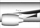
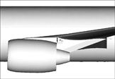
Position of TFN for the VHBR1-configuration.
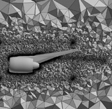
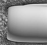
Cut through the hybrid grid along engine axis.
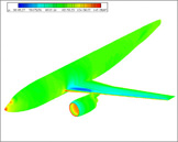
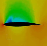
Pressure distribution for VHBR2-configuration, final result.
|
Position of TFN for the VHBR2-configuration.
Detail of hybrid grid showing prism-layer for boundary-layer discretization.
Pressure distrubution for an outboard wing-section for VHBR2.
|